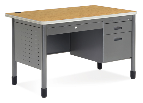
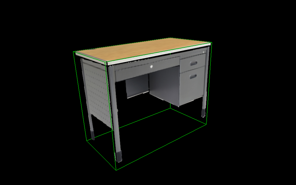
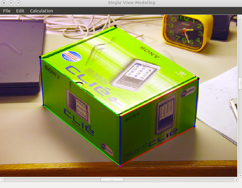
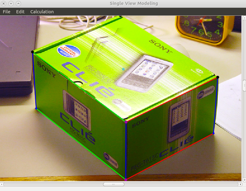
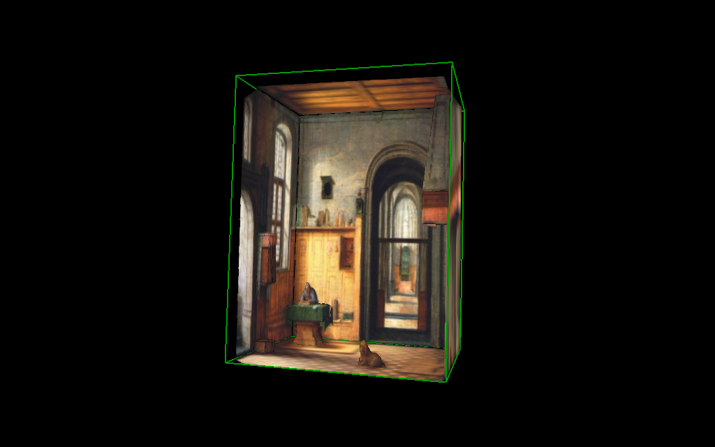
This computer vision project is to construct a 3D model from a single image plus some prior knowledge about the objects' coordinates in the image. It's based on this paper. You can download the code from here. Here is a sample 3D model (right) built from a image (left).
You should first know something about concepts like Perspective projection, Pinhole camera model, Homogeneous coordinates. A good post about homogeneous coordinates, and a good video about projective geometry. Then here are some survey [1, 2, 3] about svm. Check the following links to get a sense of single view metrology:
- Zheng Amin, Yuan Yuan
- HAIYAN YANG
- Michael Wu
- CMU: Image-Based Modeling and Rendering 13 Assignment3 and Best Results
- Cornell: CS4670/5670 computer vision Fall 2012. The design of my user interaction part comes from the experience of using their svm tool.
The tool i used to view .vrml file is view3dscene under ubuntu12.04. I highly recommend this tool.
How to calculate
vanishing point
Vanishing point is easy to understand, parallel lines in one direction will ends up on the vanishing point at infinity. Basically it needs you to manually specify two or more parallel lines (in \(X\) direction and \(Y\) direction) in the image and calculate their common intersection point (get \(X\) vanishing point and \(Y\) vanishing point respectively).
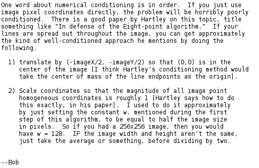
Mathmatically, to calculate a common intersection point of multiple parallel lines, it involves solving an over determined equation array problem (# of equations greater than # of variables). You can use Robert T Collins method, this will make it transform into a non-overdetermined problem, which is very easy to solve, the basic idea is (the following picture was originally an email from Collins to Steve Seitz):
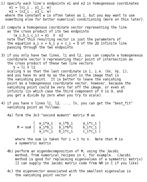
After get the \(M\) matrix, i recommend using Eigen3 package to solve the eigen values problem. Also in the other part of this project, i use Eigen3 package to manipulate matrix operations and calculate their eigen values, incluing calculating the homography matrix and \(\alpha_z\).
- After load a picture, right mouse for drugging, wheel for zooming. "Edit"-"Rescale" is for scaling to the original image size.
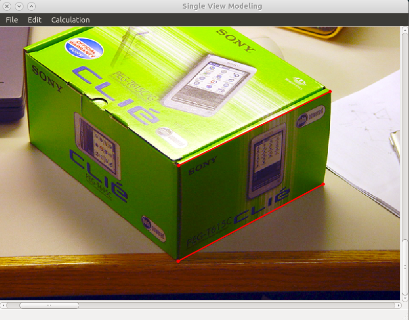
- "Edit"-"XLines", then left click to choose the parallel lines in \(X\) direction (shown with read endpoints and lines).
"Alt+d" to delete previous choosen point, "Ctrl+LeftClick" to choose one of the previous points which is under the cursor.
- "Calculation"-"XVPoint", calculate the x vanishing point, output:
Please pick up endpoints of lines pointing in X direction

------------------------------------------------
1.18115e-06    2.3329e-06    -0.00153243
2.3329e-06    4.61483e-06    -0.00301752
-0.00153243    -0.00301752    2

 Eigen Values:
-3.55187e-17
 6.91139e-08
     2.00001

 Eigen Vectors:
   0.948123    0.317904 0.000766213
  -0.317905    0.948121  0.00150876
0.000246823  0.00167407   -0.999999

Vanishing point position: (3841.3, -1287.98)
------------------------------------------------
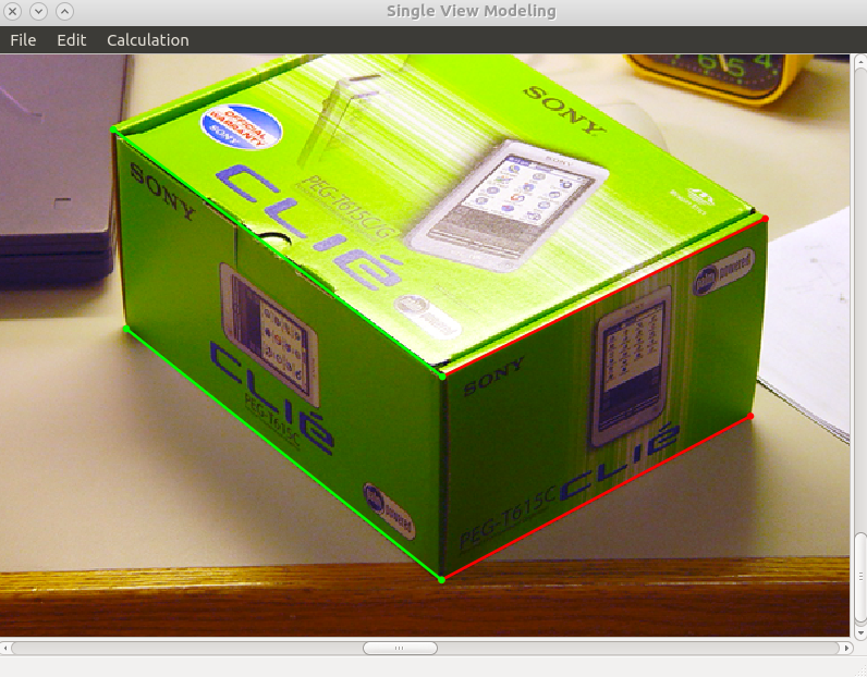
- Repeat the same step to get the y vanishing point (green endpoints and lines).
Please pick up endpoints of lines pointing in Y direction

------------------------------------------------
6.30766e-05    -8.30239e-05    0.0106216
-8.30239e-05    0.000109337    -0.0138698
0.0106216    -0.0138698    2

 Eigen Values:
-2.49691e-16
 1.98177e-05
     2.00015

 Eigen Vectors:
    0.814622     0.579968   0.00531067
    0.579992    -0.814593  -0.00693469
-0.000304136  -0.00872929     0.999962

Vanishing point position: (-2678.48, -1907.01)
------------------------------------------------
homography matrix
Basically, i use the method in this file to calculate the homography matrix. It involves LU decomposition which can be calculated using Eigen3 (I have tried to implement by myself, but the performance is bad).
The complete projection matrix \(P\) which projects a 3D(real world) homogeneous coordinate \((X,Y,Z,1)^{T}\) to a 2D(image pixel) homogeneous coordinate \((U,V,1)^{T}\) is a \(3\times4\) matrix, which is actually \([\alpha_xV_x, \alpha_yV_y, \alpha_zV_z, O]\), where \(V_x\), \(V_y\), \(V_z\) are the homogeneous coordinates for \(x,y,z\) vanishing points, \(O\) is the homogeneous coordinates for the origin. When we are talking about plane \(Z=0\), \(P\)'s third column can be ignored because \(Z\) is always equal to 0, so \(P\) becomes the homograph matrix \(H\), which is \([\alpha_xV_x, \alpha_yV_y, O]\).
Let's say we have a 3D homogenous cooridinate \((X,Y,0,1)^T\) and its corresponding 2D homogenous coordinate \((U,V,1)^T\), then \(H\) applied on \((X,Y,1)^T\) should give \((u,v,w)^T\) where \(\frac{u}{w} = U\), and \(\frac{v}{w} = V\), so \(H\) actually have only 8 independant parameters and each 3D-2D coordinate pair contributes two equations. So theoritically we only need 4 pairs to solve these parameters. Now if we already have \(V_x\) and \(V_y\), then we actually have only 4 parameters \(\alpha_x\), \(\alpha_y\), and 2 in \(O\) undetermined, so if given the vanishing points in \(X\) and \(Y\) direction, we need 2 more cooridinate pairs (they should not be colinear with any vanishing point) to calculate the left 4 parameters (which in total, still 4 pairs to determine \(H\), 2 vanishing points plus 2 extra pairs, actually using the 2 vanishing points and 2 extra pairs which are not colinear with any vanishing point, we can get another 2 extra pairs). Actually \(\alpha\) indicates the scale (or decreasing speed) in that direction, the vanishing point in that direction and 2 extra pairs which are colinear with the vanishing point will determine the scale, which is \(\alpha\).
Anyway, there are 3 ways to calculate \(H\):
- 4 non-colinear coordinate pairs
- \(X\) and \(Y\) vanishing points plus 2 more coordinate pairs which are not colinear with any vanishing point
- \(X\) and \(Y\) vanishing points plus other coordinate pairs which at least 2 pairs are colinear with \(X\) vanishing point and 2 paris are colinear with \(Y\) vanishing point, they can share one pair like the origin
Using which way to calculate \(H\) depends on what you believe, if you think you can calculate the vanishing point very accurately, then use the vanishing point, if you think you are confident about the real 3D coordinate of some point in the image, then don't use vanishing point. Of course you can use all of them which are over determined, but don't worry, LU decomposition and Eigen3 will handle this.
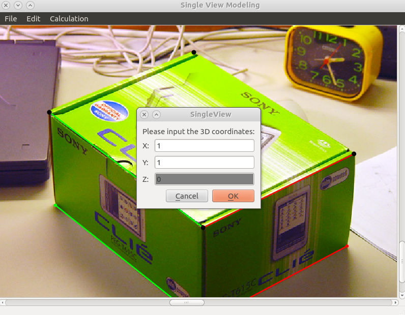
- "Edit"-"RPlane", choose a point in the image (black point) and specify its 3D coordinate, don't forget to use "Ctrl+LeftClick" to choose existed points and "Alt+d" to undo
- "Calculation"-"Homography", calculate the homography matrix, it will ask you whether you wanna use \(X\) and \(Y\) vanishing points or not (if they are already calculated in previous step), you can choose based on your requirement
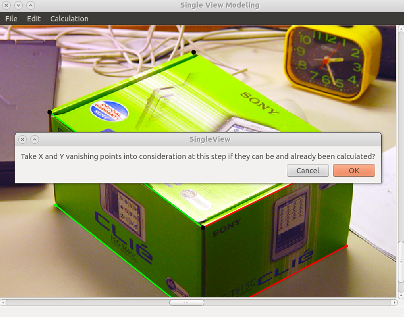
sample output (i choosed using the vanishing point here):
Please specify 4 or more points on Z=0 plane (including vanishing points on this plane's vanishing line if they can be calculated and will be taken into account) and make sure these points could form a polygon

 A:
 393.366  400.799        1        0        0        0       -0       -0
       0        0        0  393.366  400.799        1       -0       -0
 617.494  291.022        1        0        0        0 -617.494 -291.022
       0        0        0  617.494  291.022        1       -0       -0
 164.839  229.112        1        0        0        0       -0       -0
       0        0        0  164.839  229.112        1 -164.839 -229.112
 379.584  139.887        1        0        0        0 -379.584 -139.887
       0        0        0  379.584  139.887        1 -379.584 -139.887
       0        0        0   3841.3 -1287.98        1        0        0
       0        0        0        0        0        0   3841.3 -1287.98
-2678.48 -1907.01        1        0        0        0        0        0
       0        0        0        0        0        0 -2678.48 -1907.01

 b:
 0
 0
 1
 0
 0
 1
 1
 1
 0
-1
 0
-1

 Rank of [A b]:
8

 x:
  0.00308069
 -0.00410059
    0.431674
    -0.00195
 -0.00398125
     2.36275
-5.74491e-05
  0.00060507

 A*x:
-2.22045e-16
-2.22045e-16
           1
-1.77296e-10
 4.75542e-12
           1
    0.964602
      1.0028
           0
          -1
 4.44089e-16
          -1

 Homography matrix (from image to scene):
  0.00308069  -0.00410059     0.431674
    -0.00195  -0.00398125      2.36275
-5.74491e-05   0.00060507            1

 Homography matrix (from scene to image):
  218.915   -176.47   322.454
  -73.402  -125.643   328.547
0.0569898 0.0658845  0.819731
------------Point 1 -------------
 ImageCoord:
393.366
400.799
      1

 HomoMat * ImageCoord:
-1.82017e-16
-3.64034e-16
           1

 SceneCoord:
0
0
1
------------Point 2 -------------
 ImageCoord:
617.494
291.022
      1

 HomoMat * ImageCoord:
           1
-1.55439e-10
           1

 SceneCoord:
1
0
1
------------Point 3 -------------
 ImageCoord:
164.839
229.112
      1

 HomoMat * ImageCoord:
4.21147e-12
          1
          1

 SceneCoord:
0
1
1
------------Point 4 -------------
 ImageCoord:
379.584
139.887
      1

 HomoMat * ImageCoord:
0.966694
 1.00263
       1

 SceneCoord:
1
1
1
------------Point 5 -------------
 ImageCoord:
  3841.3
-1287.98
       1

 HomoMat * ImageCoord:
     17.547
4.44089e-16
          0

 SceneCoord:
1
0
0
------------Point 6 -------------
 ImageCoord:
-2678.48
-1907.01
       1

 HomoMat * ImageCoord:
 4.44089e-16
     15.1781
-2.22045e-16

 SceneCoord:
0
1
0
Note: HomoMat here is the inverse of \(H\)
\(\alpha_z\)
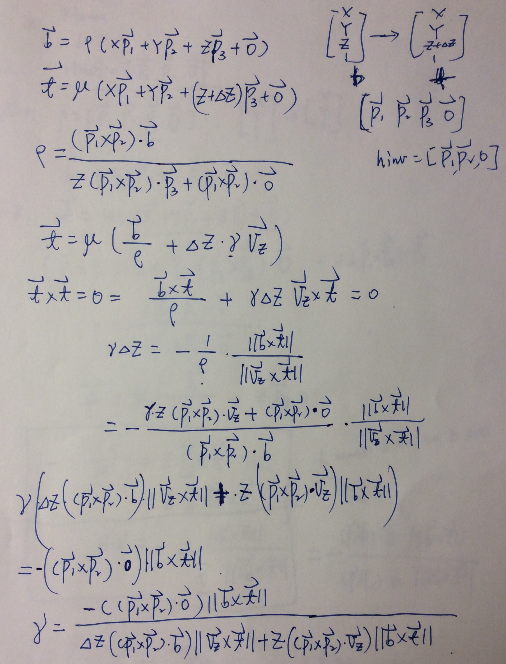
To calculate \(\alpha_z\) is to determine the third column in \(P\), you need to first calculate the \(Z\) vanishing point, and then sepecify 2 extra coordinatepairs which are colinear with \(Z\) vanishing point (which means they have the same \(X\) and \(Y\) coordinates, and think of how to calculate \(H\) with the 3rd method). The following is the derivation for calculation of \(\alpha_z\) (which is \(\gamma\)) from two scene points \((X,Y,Z)\) and \((X,Y,Z+\delta Z)\), i use the notation which should be the same as those derivation in the materials i mentioned above, but here the two points \(b\) and \(t\) can be both off plane.
- "Edit"-"Zlines" to choose z parallel lines, then "Calculation"-"ZVpoint" to calculate \(Z\) vanishing point (blue lines and endpoints)

Please pick up endpoints of lines pointing in Z direction

------------------------------------------------
5.34101e-05    -2.71212e-06    -0.0107707
-2.71212e-06    2.05445e-07    0.000310135
-0.0107707    0.000310135    3

 Eigen Values:
2.30787e-12
1.49136e-05
    3.00004

 Eigen Vectors:
   -0.107822    -0.994164   0.00359024
    -0.99417     0.107822 -0.000103379
-0.000284333  -0.00358046    -0.999994

Vanishing point position: (379.211, 3496.5)
------------------------------------------------
- "Edit"-"RPlane" to specify 2 offplane scene points, the thin white line is connected to the \(Z\) vanishing point
- After specify the first scene point's coordinate, there will be a projected point on \(Z=0\) plane and you can either choose that point as the second point or choose another off plane point if you like. Don't forget "Ctrl+LeftClick" and "Alt+d" if needed.
- "Calculation"-"Alpha" to calculate \(\alpha_z\)
++++++++++++ All 4 Check ++++++++++++++
 P1:
  218.915
  -73.402
0.0569898

 P2:
  -176.47
 -125.643
0.0658845

 O:
 322.454
 328.547
0.819731

 Vz:
379.211
 3496.5
      1

 b:
393.366
400.799
      1

 t:
392.794
542.022
      1

 z: 0 deltaz: -1

 gammaZ:
 -0.0391533

 Projection Matrix from scene to image:
   218.915    -176.47   -14.8474    322.454
   -73.402   -125.643     -136.9    328.547
 0.0569898  0.0658845 -0.0391533   0.819731
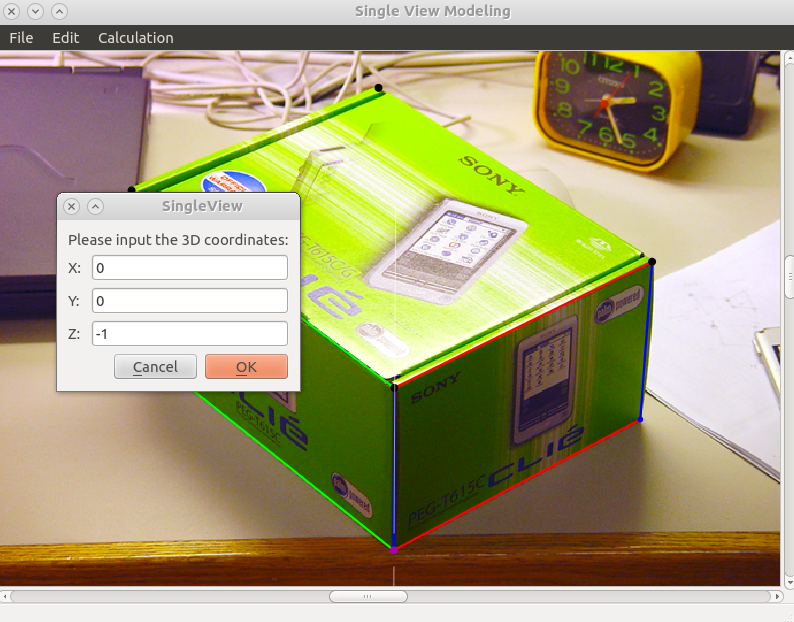
- After calculate \(Z\) vanishing point and \(\alpha_z\), we actually get the projection matrix \(P\), we can test it by "Calculation"-"Scene2Image", input the 3D scene coordinate,
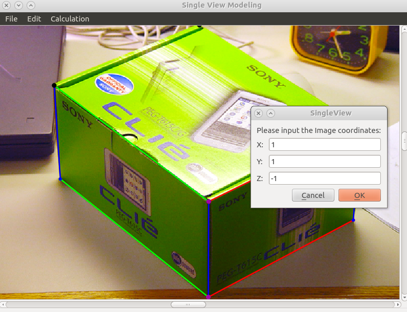
it then shows the corresponding point in the image:
How to generate texture patches and build 3D model (vrml file)
First you need to enter "Edit"-"PtPool" state, pick many points of interest in the image and using the later mentioned co-plane or co-z methods to get their 3D scene coordinates, this step will save all the points of interest in a pool, then enter "Edit"-"Polygon" state and choose points from the pool to form a polygon and use "Calculation"-"Texture" or ("Alt+p") to calculate the patches of this polygon, there are also bounding-box method or polygon method to calculate the patches. You can use "Alt+s" to switch between co-plane and co-z method if you are in "PtPool" state, or switch between bounding-box and polygon method if you are in "Polygon" (making patches using points in pool) state.
Something to clarify:
To get scene coordinate ("Edit"-"PtPool"):
- co-plane method, when the previous point and next point are on the same plane, they share the same homography matrix
- co-z method, when the previous point and next point are colinear in z direction, the homograph matrix will be updated from \([P_1, P_2, O_z]\) to \([P_1, P_2, O_z+\gamma V_z\delta z]\), actually in general, the homography matrix for plane \(Z=z\) can be written as \([P_1, P_2, O_0+\gamma V_zz]\)
Start from a point in \(Z=0\) plane, default is co-plane method, then select points of interest on this plane, when you want to jump to another \(Z=z\) plane, first "Alt+s" to switch the mode, then select the projected point on the new plane (with help of the thin white line), after selection of the first point on the new plane, the method will be automatically switched back to co-plane method. Repeat this process untill you select all the points of interest. Dont forget the usage of "Alt+d" and "Ctrl+LeftClick" when needed. Also you can press "=" to enlarge the gap on the white line, or press "-" to make it smaller.
output:
Please pick up all the points which will be used to form polygons later, start from one point in the reference plane.
You can change method state afterwards. Begin with co-plane methods. "Alt + S" could switch between co-plane and vertical methods.
Scene Coordinates: (-1.82017e-16, -3.64034e-16, 0)
Scene Coordinates: (1, -1.55439e-10, 0)
Scene Coordinates: (0.966694, 1.00263, 0)
Scene Coordinates: (4.21147e-12, 1, 0)
Scene Coordinates: (-1.82017e-16, -3.64034e-16, 0)
Scene Coordinates: (1, -1.55439e-10, 0)
Please select a previous point (Ctrl + LClick) first !
Scene Coordinates: (-1.82017e-16, -3.64034e-16, 0)
Scene Coordinates: (1, -1.55439e-10, 0)
Scene Coordinates: (0.966694, 1.00263, 0)
Please select a previous point (Ctrl + LClick) first !
Scene Coordinates: (0.966694, 1.00263, 0)
Scene Coordinates: (4.21147e-12, 1, 0)
Scene Coordinates: (4.21147e-12, 1, -1.00038)
Scene Coordinates: (2.66999e-05, -0.000287184, -1.00038)
Scene Coordinates: (0.999159, -0.000287184, -1.00038)
Scene Coordinates: (1.10566, 0.0653924, -1.00038)
Scene Coordinates: (1.10334, -0.368431, -1.00038)
Scene Coordinates: (0.847286, -0.541693, -1.00038)
Scene Coordinates: (-0.846693, 0.507535, -1.00038)
Scene Coordinates: (-0.191485, 1.26989, -1.00038)
Scene Coordinates: (0.0377504, 1.15913, -1.00038)
Scene Coordinates: (0.111889, 1.16806, -1.00038)
Scene Coordinates: (0.186364, 1.23369, -1.00038)
To get the patches ("Edit"-"Polygon"):
The problem in this step is given some nearlly co-plane 3D scene coordinates, we want to map them back to the image and using some interpolation method to get the RGB value of the scene points between pixels. My method is first calculate the plane equation, then calculate the rotation matrix which could rotate the plane into a \(Z=z\) plane, and apply this rotation operation to all the scene points and get the coordinates of their corresponding points on \(Z=z\) plane, then we find the polygon formed by these points (polygon method) or a bounding box (boundingbox method), to iterate the polygon area or the bounding box area, we need to set a scale which indicates the granularity of the patch (you need to adjust the scale value in makePatch() function according to the scene coordinates you input), for example, a 1 by 1 scene patch will have 100 by 100 points inside if you set scale to be 0.01.
How to get the RGB value of a point inside the polygon or boundingbox, i will first rotate it from \(XY\) plane to 3D scene position, then use projection matrix \(P\) to find its scene pixel, then use Bilinear Interpolation method to get its RGB value.
This video show we first use bounding box method to create a rectangle patch for 3 selected points, then "Alt+s" switch to polygon method and get a triangular patch from 3 points, next we show how to create a more complex polygon patch (when using polygon method, the points should be selected on clock-wise or counter clock-wise order). Also you can pick some points which are some tilted plane, it doesn't have to be horizontal or vertical plane.
output:
Please select at least 3 points for each plane and make patch by press "Alt + P" or click "Texture" in "Calculation" menu, you can change TextureMethod (BoundingBox method or Polygon method) with "Alt + S", default: BoundingBox method

 Plane coefficients:
 1.55483e-10
     1.00029
-0.000287158
-3.33004e-16

 Plane coefficients:
 1.55483e-10
     1.00029
-0.000287158
-3.33004e-16

 Plane coefficients:
 2.41128e-14
-3.58101e-13
    -2653.23
     2654.23
To make vrml model:
It takes me a long time to figure out what is the grammer of vrml model, the most simplest form is like the Bookshelf example, by clicking "Edit"-"Save" function, the tool will combine all the patches together and create the .wrl file automatically.
When making point pools and generating patches, it's better to use incremental methods, which means add some points to the pool, then generate some patches using the newly add points, then add some other points to the pool and generate other patches. It's important to check at each time whether the scene coordinates of newly add points are acceptable, especially when you are jumping to another plane, because if there are some errors at some point, it will leads to incrementally larger error for the later added points. Basically, in this process, we have to be very careful and patient and make sure different paths to some point is consistent in an acceptable level.
Paint Sample
For irregular object as the man and lion in this paint sample, when generating patches, you can first pick a rectangle which is big enough to hold the object, then use the intelligent scissor tool to pick out the object from old patch and use the picked out image as new patch.
All the original pictures, generated patches and vrml models can be downloaded from here.